


One of the most important points to consider one a build is the load-bearing choices. On one retrofit, you watch a “missing stud” turn into a roof sag, like a broken link snapping a chain. You don’t get structural integrity by hope; you get it by tracing a continuous load path from roof to foundation, checking load combos and safety factors, and choosing spans, materials, and connections that meet code and control deflection. But one overlooked joint can reroute forces in ways you won’t spot until…
Trace the Load Path for Structural Integrity

Even if your design checks out on paper, you can still lose structural integrity if you can’t trace a continuous load path from every applied force to a defined support.
You should map forces through diaphragm, collector, chord, member, connection, and foundation in that order, then confirm every handoff has positive attachment and adequate stiffness.
You can’t let Innovative materials or aesthetic considerations interrupt continuity: a cantilevered feature, a slotted connection, or a thin façade panel can become an unintended fuse.
You should detail connections so shear, tension, and compression transfer without relying on friction or “typical” notes.
In your calcs and drawings, name each load transfer element, flag discontinuities, and require inspection hold points where the path is concealed.
Identify Load Cases, Combos, and Safety Factors
Now that you’ve traced the load path, you must define the critical load cases that actually govern strength and serviceability under your governing code (e.g., wind, seismic, thermal, impact, construction, and accidental).
You then build load combinations that capture worst‑credible interactions and apply partial safety factors and resistance factors where the code intends, not where it just “feels conservative.”
If you misclassify a case or stack factors blindly, you’ll either miss a brittle limit state or overdesign without reducing risk.
Defining Critical Load Cases
Where do structural failures actually start—at the member, or in the assumptions baked into your load cases? You define critical cases by mapping every credible action: dead, live, snow, wind, seismic, thermal, soil, ponding, equipment, and accidental impacts.
Follow your governing code’s load definitions and occupancy categories, then capture boundary conditions that change demand: diaphragm continuity, fixity, second‑order effects, and load path discontinuities.
Don’t ignore Construction sequencing; temporary shoring removal, partial composite action, and staged backfill can govern more than the final state.
Tie loads to Material durability risks: corrosion allowance, creep, shrinkage, moisture cycling, and fire exposure alter stiffness and tributary distribution.
Build combinations that reflect concurrent actions and the controlling directionality, and document rationale for reviewers and future modifications.
Applying Safety Factors Wisely
How do you add safety without hiding risk behind inflated numbers? You start by mapping load cases to real failure modes: gravity, wind, seismic, thermal, impact, and temporary erection loads.
Then you apply code-defined combinations (ASCE 7/EN 1990) and pick the governing envelope, not a convenient average.
Use partial factors to separate uncertainty: actions, resistance, and consequence class.
Don’t “double factor” by mixing ASD/strength methods or stacking conservative assumptions in analysis and detailing.
Check serviceability separately so deflection and vibration don’t get ignored by high strength margins.
Fold in Material durability by reducing capacity for corrosion, creep, or fatigue where exposure demands it.
Respect Construction sequencing; temporary bracing and pour stages can govern.
Document assumptions and trigger reviews.
Match the Structural System to the Loads

You’ve set the load cases and factors; now you must map every gravity and lateral demand to a continuous, code-compliant load path from diaphragm to collector to frame to foundation.
You’ll select framing that matches those demands—beam/column, wall, truss, or composite—so stiffness, ductility, and connection capacity align with the governing limit states.
You can’t ignore lateral forces, so you’ll define the LFRS, check torsion and drift, and verify diaphragm and anchorage continuity to prevent brittle, high-consequence failure modes.
Identify Load Paths
Why guess at strength when the loads already tell you the correct structure? You identify load paths by tracing gravity, lateral, uplift, and seismic forces from roof and floors through collectors, diaphragms, walls/frames, and into foundations and soil.
You verify continuity: every load needs a direct line without offsets, soft stories, or discontinuous shear transfer. You check torsion from plan irregularity, re-entrant corners, and stiffness mismatches, then flag where code requires collectors, chords, and boundary elements.
You coordinate openings and penetrations so they don’t sever the path or overload adjacent members. You also account for Material durability at interfaces where moisture or corrosion can weaken connections.
During Construction sequencing, you maintain temporary stability so partially complete paths don’t trigger progressive collapse or exceeding drift limits.
Select Appropriate Framing
Where do the loads want to go once they leave the diaphragm and hit the vertical system? You’ve got to choose framing that keeps that route direct, continuous, and code‑compliant.
Match gravity demands to member capacity and stiffness: studs or posts for axial load, beams/girders for spans, and bearing walls where reactions can land on aligned supports. You can’t “make it work” with oversized headers if the supporting jambs crush or the foundation point‑loads exceed allowable soil pressure.
Detail connections so they transfer forces without eccentricity or brittle failure, and verify nailing/fastening schedules per the adopted code.
Consider Material durability at moisture interfaces and corrosion zones. Don’t ignore Aesthetic harmony, but don’t let it drive unsafe offsets.
Account For Lateral Forces
Once gravity load paths line up, lateral loads become the next failure driver, so match your vertical system to the wind and seismic demands it must resist. You don’t get Lateral stability by accident; you detail it with a defined lateral-force-resisting system—shear walls, braced frames, or moment frames—continuous to the foundation.
Check code-required diaphragm design, collectors, and chord forces so loads transfer without weak links. Verify overturning, sliding, and uplift, and anchor into competent soil or piles with explicit load paths.
Control drift to protect cladding, partitions, and egress; excessive story drift signals overstress and P-Δ amplification. For seismic resilience, avoid soft stories, torsional irregularities, and discontinuous walls.
Specify nailing, hold-downs, and connections to meet seismic detailing and inspection requirements.
Size Spans and Supports to Control Deflection
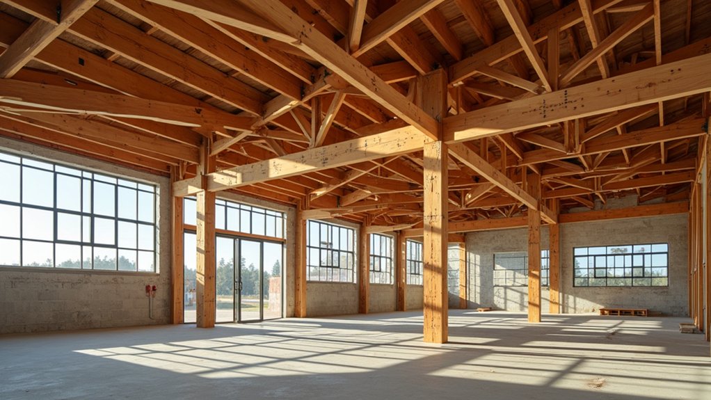
Even a small increase in span can blow up deflection, so you can’t treat member sizing and support layout as an afterthought. Check serviceability limits before strength: use code deflection criteria (e.g., L/360 floors, L/240 roofs, stricter for brittle finishes) and verify creep, vibration, and differential movement.
Shorten spans with intermediate beams, bearing walls, or closer joist spacing, and confirm load paths and bearing lengths meet minimums. Detail supports to avoid eccentricity and rotation; provide blocking, bridging, and diaphragm ties where required.
Coordinate construction sequencing: temporary shoring, wet concrete loads, and early loading can exceed final-stage assumptions. Control moisture and storage to protect material durability so member stiffness stays predictable.
Document tolerances; sag can telegraph into finishes and drainage.
Choose Materials for Long-Term Structural Integrity
Because serviceability and durability drive most lifecycle failures, you should choose materials by how they hold stiffness, strength, and connections over decades—not just by initial capacity.
Start with exposure class and environment: chloride, sulfate, freeze–thaw, UV, humidity, and temperature cycles. Verify code-required durability provisions (e.g., concrete cover, w/c limits, preservative treatment, corrosion protection) and confirm compatibility with fire-resistance ratings.
Evaluate creep, shrinkage, relaxation, and fatigue where cyclic loads or long spans govern; adjust design values for moisture, duration of load, and temperature per the applicable standard.
Specify corrosion-resistant or protected steel in coastal/industrial zones, and select concrete mixes that limit permeability.
Balance Material durability with aesthetic considerations, but don’t let finishes mask risk or hinder inspection later.
Detail Connections That Preserve Load Transfer
Where do long-term failures usually start—if not at the connections that must keep transferring load as materials creep, shrink, corrode, and cycle? You reduce that risk by treating Connection details as primary structure, not draft notes.
Specify continuous load paths and verify each interface’s capacity, stiffness, and deformation limits under service conditions. Detail bolts, welds, and anchors for slip, prying, and eccentricity, and call out installation tolerances you’ll actually inspect.
Provide edge distances, embedment, and minimum fastener spacing per applicable codes and manufacturer ESRs. Prevent moisture traps, isolate dissimilar metals, and maintain required fire or corrosion protection.
Don’t rely on friction alone; design positive bearing and confinement so load transfer remains reliable over decades.
Design for Wind and Earthquake Structural Integrity
When wind gusts and seismic pulses reverse demands in seconds, you can’t count on nominal strength—you must deliver a continuous, redundant lateral system that stays stable through drift, uplift, and cyclic degradation.
Size and place shear walls, braced frames, or moment frames to satisfy ASCE 7 wind pressures and seismic base shear, then check torsion, diaphragm chords, collectors, and boundary elements for overstrength actions.
Control story drift to protect cladding, egress, and nonstructural components, and detail hold-downs and anchorage for uplift and overturning.
Balance aesthetic considerations with stiffness: avoid soft stories, irregular setbacks, and discontinuous lines of resistance.
Plan construction sequencing so diaphragms, temporary bracing, and load paths exist at every stage, not just at final completion.
Add Redundancy and Verify With Inspections/Tests
Even if your analysis meets ASCE 7 demand, you still need redundancy in the lateral and gravity load paths and you must prove it in the field with inspections and testing.
Use redundancy planning to avoid single-point failure: alternate collectors, continuous ties, diaphragm chords with backup load paths, and connections that can redistribute forces after local damage.
Detail for ductility and robustness per AISC/ACI provisions, and verify special seismic requirements where applicable.
Then enforce inspection protocols under IBC Chapter 17: verify rebar size/placement, weld procedures, bolt pretension, embedment depth, anchor edge distance, and concrete strength.
Specify NDT for critical welds, proof-load or torque tests for anchors, and pull tests where tolerances are tight.
Close the loop with submittals, RFIs, and as-built documentation before concealment.
Frequently Asked Questions
How Do Permits and Inspections Affect Structural Integrity Decisions?
Permits and inspections force you to justify structural choices against Building codes and Safety standards, so you document calculations, approved materials, and connections. Inspectors verify critical stages, flag deviations, and you correct risks before occupancy.
What Is the Typical Cost Impact of Stronger Load-Bearing Systems?
You’ll typically pay 5–20% more for stronger load-bearing systems—sometimes a jaw-dropping premium with seismic detailing. Material selection drives it; Cost estimation must include code-required connections, inspections, and reduced failure risk.
How Can I Tell if a Wall Is Load-Bearing Without Opening It?
You can’t know with certainty, but you can infer: check Wall indicators and Structural clues—wall aligns with beams/joists, sits over foundation, continues upstairs, supports roof ridge, resists code-permitted removal. Verify via plans/engineer.
When Should I Hire a Structural Engineer Versus a General Contractor?
You should hire a structural engineer when you alter load paths, spans, or foundations, or need stamped calculations; hire a general contractor for permitted execution. Engineers handle design considerations and material selection to reduce code risk.
How Do Renovations and Remodels Change a Building’s Load-Bearing Capacity?
Renovations can reduce or increase load capacity when you remove walls, cut joists, add openings, or change roof loads. You’ll often need Wall reinforcement and Foundation reinforcement to meet code, prevent deflection, and avoid overstress.